Update: code is now uploaded on {Github}.
4D Camera and GIF output
--- Day 01 ---
Jul 09 2025
Today I started working on the project.
I started off by cleaning up my code for raytracing significantly and refactoring GIF rendering and removing all of the OpenGL window work.
I also had to switch to C++17 for std::variant.
I should have working GIF output now, but I don't have a way to test it without creating a scene, and a simple render.
So for now, I am working on the simple raymarching.
I have created structs for two objects, a hypersphere (3-sphere) and a hyperplane.
I then define Object as a variant of the two types of objects, and define Scene simply as a vector of objects.
I was orignally getting lots of errors when I tried implementing this with C tagged unions, but I realized that C++ has some different quirks than C, so I had to learn to use C++ variants.
--- Day 02 ---
Jul 10 2025I changed the second object from a hyperplane to a halfspace for now. distance we have already stepped in the given direction. Additionally, there is the question of how to scatter when we hit a particle. The simplest answer, and the one I chose to implement is to simply choose a new direction at random. I'll probably add a hyperplane later, but for now, I think the simplicity of the halfspace is prefered.
One problem I seem to have is that too many of my rays die too early without reaching a light source. This is because with a set number of permitted steps, the amount of computation for a simple path is greatly increased. This makes the renders dark, like we might have already seen. When the extinctionis high , the likelyhood that particles make it to a light source at all is very very negligible. And since I don't have NEE (due to not having information about where light sources are...) volumetric fog will cause darkness.
I have written up both of the SDFs for the two object types I have right now, using aswitch on the variant::index().
I finished writing up the camera.
The way I have set up the camera is that it contains information about its location and 4 orthonormal vectors which form its heading.
Additionally, the function nextCamera updates the camera for the next frame of the GIF based on its current state, thus shifting the camera position.
Simple Raymarching
Today, I have also written a simple raymarcher that uses the SDFs to simply check if there is an intersection or not, and colour white if there is. Like this, I can create simple renders of the 3D hyperplane the camera is pointing in!
I have 2 below, one which is a static render, and the second being a render with the camera moving in the 4th dimension. Both scenes are of two hyperspheres with a halfplane, where colouring is based on the atan of a component of the intersection position. This colouring method is currently hard coded and something that I'll change (it's not very pleasant to look at either).
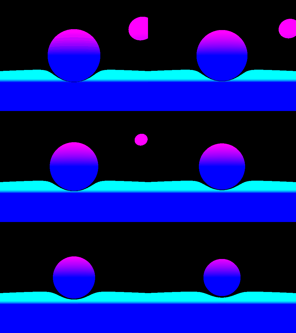
Here you can clearly see that as we move into the orthogonal direction, the spheres seem to "get smaller". This is just because the sphere slice of the hypersphere we are observing is smaller in the camera's new hyperplane.
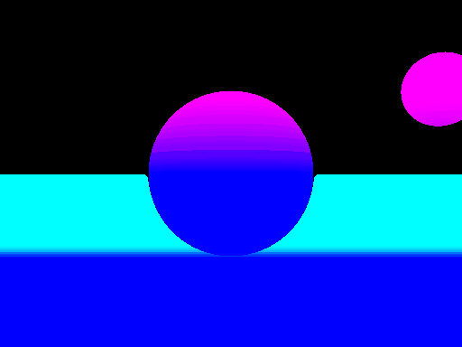
As you can see, there is undesirable warping of the shape of the halfplane near the hypersphere and near the horizon. This is because the halfspace and rays ends up at grazing angles near the horizon, and near the edge of the sphere, rays have to spend many steps as well. Thus, both of these issues can be resolved with more marching steps, like in the render below (which is only one frame).
--- Day 03 ---
Jul 11 2025Today, I started off with gradient approximation at the hit location. From knowing which object yielded the smallest SDF, we can approximate that object's SDF's gradient at the hit location to determine the normal direction. The normal is given by n defined as follows (i, j, k, l are the standard 4D unit vectors, f is the sdf of the object, and p is the hit position).
n = norm(m)

m.x = f(p + εi) - f(p - εi)
m.y = f(p + εj) - f(p - εj)
m.z = f(p + εk) - f(p - εk)
m.w = f(p + εl) - f(p - εl)
From this, we can shade our hit location according to the normal position to get some sort of idea of if our normals our correct. Renders in figure 3 and 4 show a single hypersphere with normal shading.
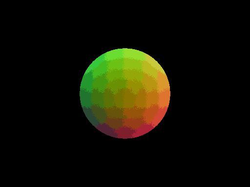
One interesting thing to note is that we almost form "cells" of colour in the first example. This probably relate to intersections where the w component of the normal is nearly 0, and is likely a floating point rounding issue. As you will see in the next render though, this is a negligible edge case, and the result is not pronounced.

In this render, we can see that as we move farther into slices of the hypersphere with larger w components, the overall blue in the sphere increases.
Finally, if you are wondering (for example) why the reddest spot in Figure 3 is not the rightmost, it is because at the rightmost point of the sphere, the green and blue components will be half. We have to transform a range from [-1, 1] to [0, 1] for each of RGB, so it won't be pure red.
--- Day 04 ---
Jul 12 2025Today, I just worked on creating a scene that I like. So far I only have the hypersphere and halfplane primitives, so I set up a scene with 2 hyperspheres in a room made of halfplanes. The hyperspheres have varying w components and radii.

I had to increase the raymarching intersection epsilon to get the room to render properly without black edges.
Material Specification System
--- Day 05 ---
Jul 13 2025
The implementation of the material system required me to redefine an object to not simply be a geometry, but to consist of both a geometry and a material.
I have material as a variant of glass, mirror, and textured materials for now.
This mirror material uses the normals to reflect the rays. As you will see though, what I thought was going to be a negligible problem (inaccurate normals) will become very noticable.
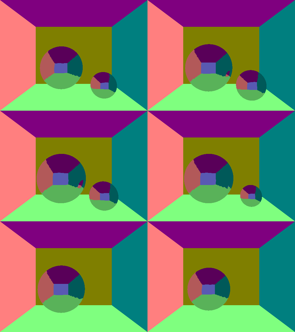
I definitely need a way to fix this. Also, I had some issues with rays getting infinitely reflected on mirror surfaces because it is infinitely registered as reflection. I fixed that temporarily by shifting the position of the reflected ray has to start at an offset away from the sphere.
One interesting code architecture choice is that I am letting the texture be a std::functional<float4, float4>.
Thus, the texture can be specified as any function of position and surface normal.
--- Day 06 ---
Jul 14 2025
I started off today with reflecting on what I did yesterday, and I realized that yesterday I spent a lot of time trying to fix avoiding a ray getting infinitely reflected.
Really, all I needed was a check on the value of dot(n, d) where d is the ray direction.
If this value is negative, then we reflect, otherwise, we just let it march.
And so with that, I tried to render the sphere scene to no avail, just black spheres.
But increasing the marching intersection epsilon and increasing the max number of steps for a ray yielded an image.
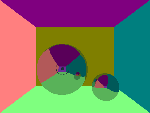
Surprisingly, the wonky steppyness that I was getting earlier is also gone... The render time is extremely high, as we may expect, though, so I think that I will take an aside to work on getting parallel computing working.
--- Day 07 ---
Jul 15 2025Starting off with execution time speedups, I started with working on implementing some sort of concurrency or parallelism. I decided to use (OpenMP), because it seems to be rather straightforward. Here is the time takes to render the scene in figure 7 with and without parallelism.
Without parallelism
real	0m3.180s
user	0m3.153s
sys	0m0.017s
With parallelism
real	0m0.142s
user	0m6.107s
sys	0m0.078s
As you can see, the speedup is substantial.
And with that speedup, here is a more flushed out render of the two mirror hyperspheres scene.
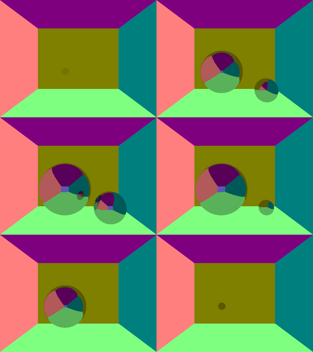
--- Day 08 ---
Jul 16 2025Today I refactored the material system with one objective in mind: to allow for one object to have different materials based on where on the material you are. To accomplish this, each object has a geometry, and a material map. The material map is a function which returns a material based on position and normal.
And with this new material system, I wanted to show that rays which are reflected can go into a different subspace. To this end, I setup the material map as follows for the walls:
MaterialMap walls = [](float4 p, float4 n) {
    float4 nn = 0.5f * n + float4(0.5f);
    return Light{(nn.x + 0.5f * nn.z) * RED + (nn.y + 0.5f * nn.z) * GREEN + p.w * BLUE};
};
And with this material, if we render one frame with the w component as 0, we get the following:
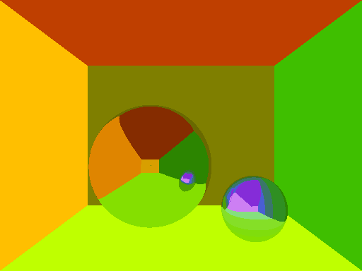
From here, we can evidently see that the rays reflecting from the small hypersphere get bounced out of the camera's hyperplane. This is because the center of the smaller hypersphere is not in the camera's hyperplane (it has a different w component).
Fresnel Refraction
--- Day 09 ---
Jul 22 2025
I started off today with a refactor of the raymarching algorithm by having a queue of RayInfo rays which contain the ray we are currently tracing, as well as the current accumulated colour and "tint" associated with the ray.
The reason that I include this is because I would like the Fresnel refraction to be exact and to accomplish this, I need to have the rays split into 2.
While I could optionally keep this information in the start and use explicit recursion, this would not be good as I keep a very high ray marching recursion depth, and I would be limited by the stack recursion depth.
Also, it is good to note that I had to change the closest intersection to use the absolute value of the SDF since we'll be marching inside an object. In order to calculate the refracted ray we also need to know both the index of refraction before and after refraction. To determine this, I add a condition that the objects in the space cannot overlap, and it they do, raymarching behaviour at overlapping spaces is undefined.
I then spent the rest of the day refactoring all of the code to allow for sufficient information when calculating the resulting rays from an intersection.
--- Day 10 ---
Jul 23 2025
Today, I finished the refactoring. I added a material for air, and also changed the way I match over variants to avoid using indices and start using std::holds_alternative.
I implemented refraction according to (this formula) on the vector form section of the Snell's Law wikipedia.
I seem to be having some issues though, because my render is ending up black like the following.
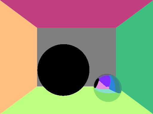
So, after some time, I figured out what the issue is. I seem to always register a hit once I hit a glass surface regardless of where we are in relation to the glass surface. This turned out to be because I scoped certain variables incorrectly and they didn't reset in value like they should have. So far though, I just have either total internal reflection or refraction, and no Fresnel refraction. Here is an example render though, where the big hypersphere is a glass sphere and the smaller one on the right is a mirror.
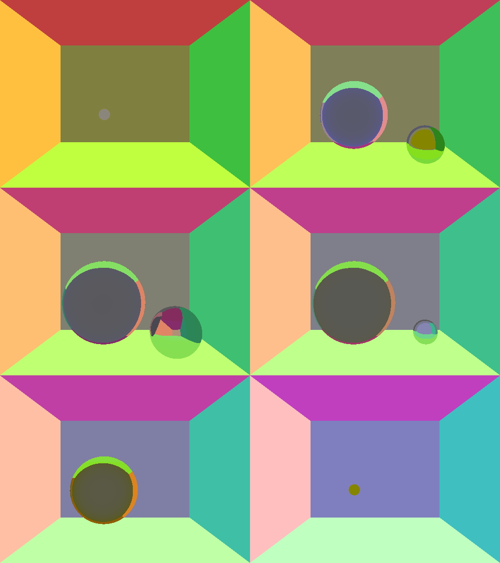
With this, there are two interesting things to notice.
- The w component of the position corresponds to the blue channel of the wall colour
- I added two walls with normals in the w direction which are visible as mossy green and lavender in the glass and mirror
--- Day 11 ---
Jul 24 2025
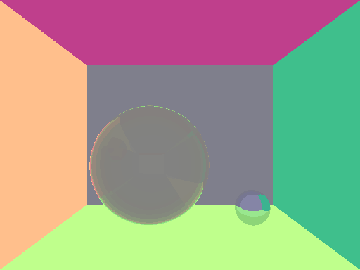
In accordance to (Schlick's approximation), I implemented Fresnel refraction.
There was a hiccup relating to having a queue which grew indefinitely because I never seemed to have a termination statement that was met.
This was due to an error in implementing the reflectance coefficient, in which the sign I assumed for the vectors l and n was incorrect.
I referenced the "Background: Physics and Math of Shading (Naty Hoffman)" course notes for a (SIGGRAPH 2012 course) for more information about the Schlick approximation.

SDF Manipulations
The purpose of this section is to to the following:
- introduce hypercube geometry
- geometry infinite tiling
- geometry rounding
- geometry onioning
- modify SDFs for translations and rotations
- remodel existing geometry to use transformations instead of having position parameters
--- Day 12 ---
Jul 25 2025Today, I have introduced hyperbox geometry, and added SDFs for translations and rotations. I have additionally remodelled the existing hypersphere and halfplane code to be described by simply radius and normal vectors, and to leave the position and offset as results of translation. Here is an example of a hypercube that is rotated into an interesting position.

--- Day 13 ---
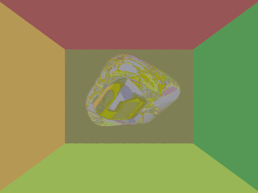
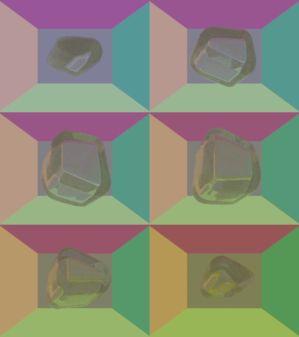
Jul 26 2025I finished off the other SDF manipulations like onioning and rounding. In fact, here is a onioned, rounded hyperbox with Fresnel refraction.
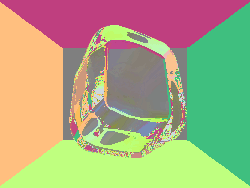
There is a lot of noise in this render. This is something that we may expect because some paths are terminated very early compared to how long they should proceed. This means we potentially only get less contributing paths. When volumetric fog and volumetric rendering is added, this should be remediated somewhat.
The code for describing this scene is as follows:
MaterialMap wall = [](float4 p, float4 n) {
    float4 nn = 0.5f * n + float4(0.5f);
    return Light{(nn.x + 0.5f * nn.z) * RED
               + (nn.y + 0.5f * nn.z) * GREEN
               + (0.25f * p.w + 0.5f) * BLUE};
};

MaterialMap glass = [](float4 p, float4 n) {
    return Glass{Colour(0.7f), 1.4f};
};

Geometry room   = Hyperbox{float4(2.0f, 1.5f, 4.0f, 2.0f)};
Geometry roomT  = Translation{float4(0.0f, 0.0f, -2.0f, 0.0f), &room};
Geometry roomTO = Onion{0.1f, &roomT};

Geometry box    = Hyperbox{float4(0.5f)};
Geometry boxR   = Rotation{inverse(rotateAlong(0, 3, 20,
                                   rotateAlong(1, 3, 45,
                                   rotateAlong(1, 2, 30,
                                   rotateAlong(0, 2, 30, linalg::identity))))), &box};
Geometry boxRR  = Round{0.3f, &boxR};
Geometry boxRRO = Onion{0.2f, &boxRR};

scene.objects.push_back(Object{roomTO, wall});
scene.objects.push_back(Object{boxRRO, glass});
I didn't mention this yesterday, but the way that I do rotations is by specifying the inverse rotation matrix.
In specific, the inverse rotation matrix should by an isometry and have determinant 1.
Since it's hard to come up with such rotation matrices, I decided to be able to construct such a matrix via the ability to rotate along a certain plane at a time.
Namely, the function rotateAlong will replace the columns of the rotation matrix at specified indices with two new vectors which are linear combinations of the columns.
Here is the actual implementation
float4x4 rotateAlong(int index1, int index2, float angleDegrees, float4x4 rotation) {
    float angleRadians = angleDegrees * DEG_TO_RAD;
    float4 n1 =  float(cos(angleRadians)) * rotation[index1]
               + float(sin(angleRadians)) * rotation[index2];
    float4 n2 = -float(sin(angleRadians)) * rotation[index1]
               + float(cos(angleRadians)) * rotation[index2];
    rotation[index1] = n1;
    rotation[index2] = n2;
    return rotation;
}
--- Day 14 ---
Jul 28 2025Today I finished the infinite tiling code. I decided to implement tiling generally by allowing the user to specify a function which given a point in space, returns the center of the closest tiling cell. Then, I can denote the D4 tiling scheme as follows:
TilingCellMap d4Tiling = [](float4 p) {
    float4 tilingCell;

    int lx = std::ceil(p.x - 1.0f), rx = std::floor(p.x + 1.0f);
    int ly = std::ceil(p.y - 1.0f), ry = std::floor(p.y + 1.0f);
    int lz = std::ceil(p.z - 1.0f), rz = std::floor(p.z + 1.0f);
    int lw = std::ceil(p.w - 1.0f), rw = std::floor(p.w + 1.0f);
    lz = std::max(lz, 0); rz = std::max(rz, 0); // cut off points with negative z

    float distance2 = std::numeric_limits<float>::max();
    for (int x = lx; x <= rx; x++) {
    for (int y = ly; y <= ry; y++) {
    for (int z = lz; z <= rz; z++) {
    for (int w = lw; w <= rw; w++) {
        if ((x + y + z + w) % 2 != 0) continue;
        float4 candidate = float4(x, y, z, w);
        if (distance2 < length2(candidate - p)) continue;
        distance2 = length2(candidate - p);
        tilingCell = candidate;
    }}}}
    return tilingCell;
};
Note that the way to exclude points with negative z component is to change lz and rz.
I was originally first clamping the z component of p before performing any operations, but this is incorrect since the SDF function will think it's closest to a hypersphere with z value 1 instead of a closer sphere with z value 0 sometimes.
This is the type of artifact that I was getting:
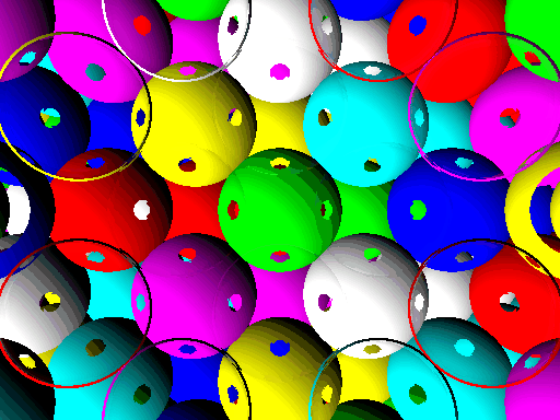
So I fixed this, and used hyperspheres of radius 1 / sqrt(2) with the following shading scheme:
MaterialMap d4Shading = [d4Tiling](float4 p, float4 n) {
    std::vector<Colour> colours = {RED, GREEN, BLUE, YELLOW, TEAL, PINK, WHITE};
    int4 ip = apply([](float q) {return int(q);}, d4Tiling(p));
    int index = (2 * ip.x + 3 * ip.y + 5 * ip.z + 7 * ip.w) % colours.size();
    if (index < 0) index += colours.size();

    return Light{colours[index] * (0.5f + 0.5f * dot(n, normalize(float4(-1.0f))))};
};
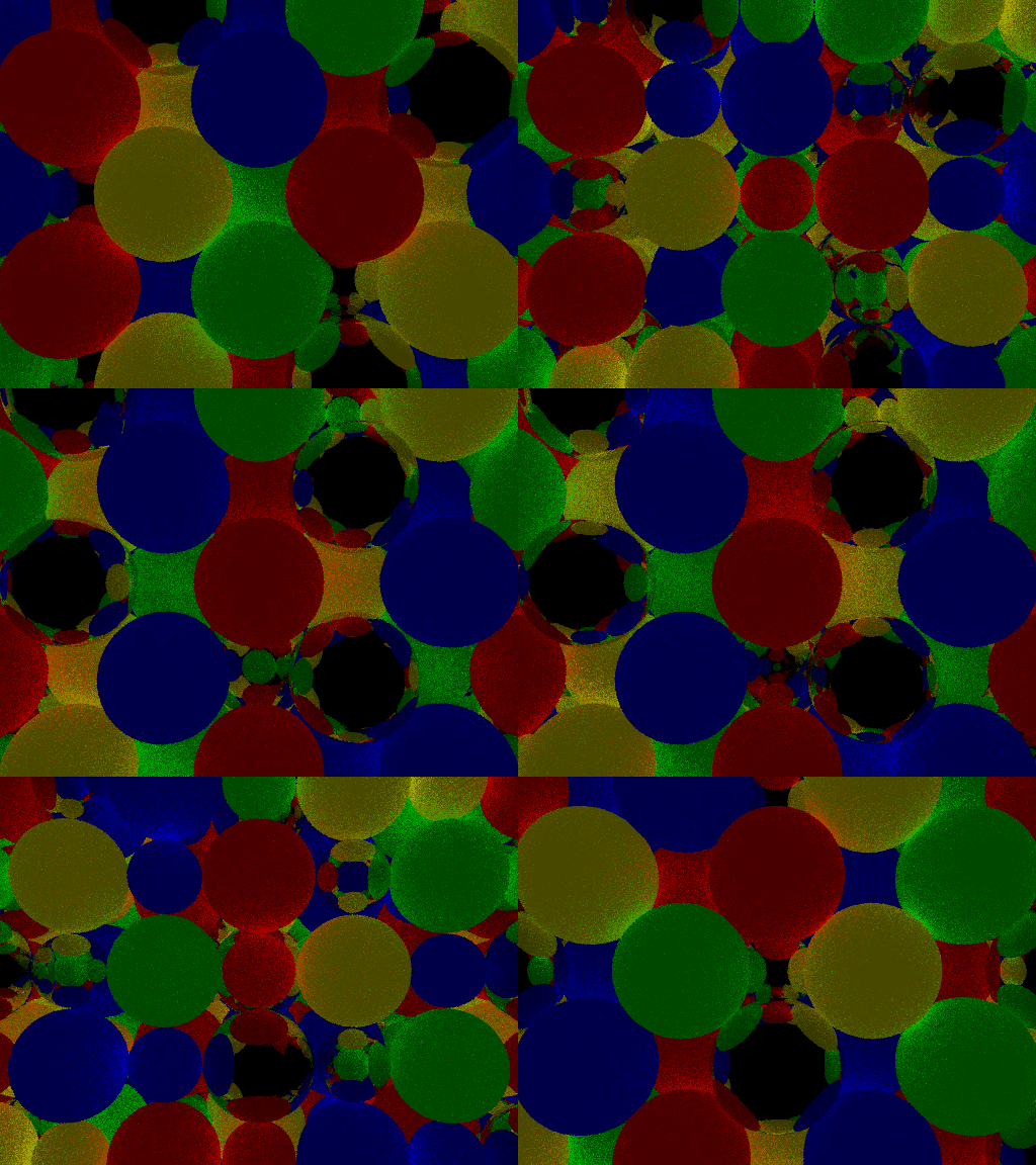
This yields the following visualization of the D4 packing of hyperspheres, the densest packing of hyperspheres in 4 dimensional real space.
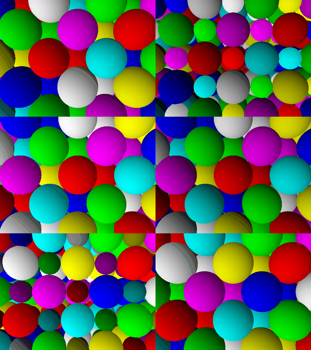
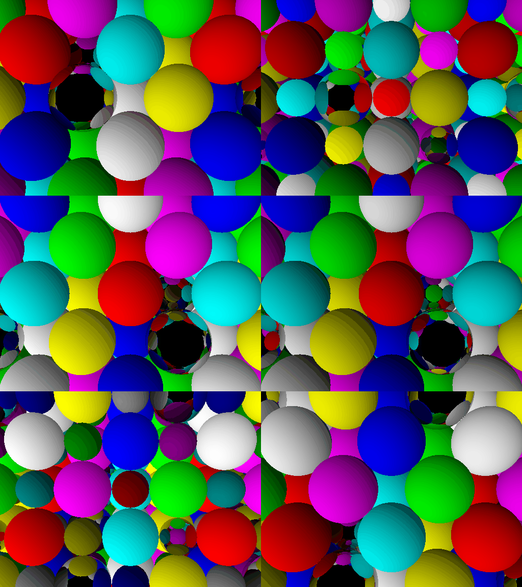
You can see in some intermediate frames that there are an infinite number of these spheres. This is quite cool to observe since we have only one SDF for this whole object and only one shading rule. This is why I opted to let each object have a material map rather than a fixed material. In fact, since we defined our objects to have a material map, we can even make some of the spheres mirrors, like so:
MaterialMap d4Shading = [d4Tiling](float4 p, float4 n) {
    std::vector<Colour> colours = {RED, GREEN, BLUE, YELLOW, TEAL, PINK, WHITE};
    int4 ip = apply([](float q) {return int(q);}, d4Tiling(p));
    int index = (2 * ip.x + 3 * ip.y + 5 * ip.z + 7 * ip.w) % (colours.size() + 1);
    if (index < 0) index += (colours.size() + 1);

    Material m;
    if (index == (int) colours.size()) m = Mirror{0.7f * WHITE};
    else m = Light{colours[index] * (0.5f + 0.5f * dot(n, normalize(float4(-1.0f))))};
    return m;
};
Which yields the following render:
Pathtracing with Parallel Computation
--- Day 15 ---
Jul 30 2025
The start for this is to first introduce tone mapping to shift from a space described by radiance and luminance to one which is described by pixel colour value.
For now, I have opted to use Reinhard tone mapping with a slight modification.
If V is the luminance of the pixel before mapping, then the luminance after tone mapping will be Ar / (Ar + 1) where A is some constant value.
This is slightly more general than the typical tone mapping while still being really bare-bones.
Higher values of A will result in overexposure, but lower values will result in images too dark.
I've found A = 2.0f seems to be an acceptable middle ground.
The second thing that I've done is to write a randomPixelRay function which randomly and uniformly samples an eye ray passing through the passed pixel.
Along with this, I've introduced sampling for the render by averaging the resulting radiance for the rays for each pixel.
Recall that the parallel computation aspect is something that I've already implemented earlier.
Revisiting Fresnel and other BRDFs
--- Day 16 ---
Jul 31 2025I already have support for the BRDF of mirror surfaces and black body light sources. I am now looking at supporting the BRDFs of the following materials:
- Glass via Fresnel refraction
- Lambertian surfaces (ideal diffuse)
- Glossy materials via microfacets
The implementation of this for glass is quite easy since I already ahve the diverging paths version implemented. All I have to do is choose to either refract into the material or reflect with the probability given by the computed coefficient. It returns an image like the following:
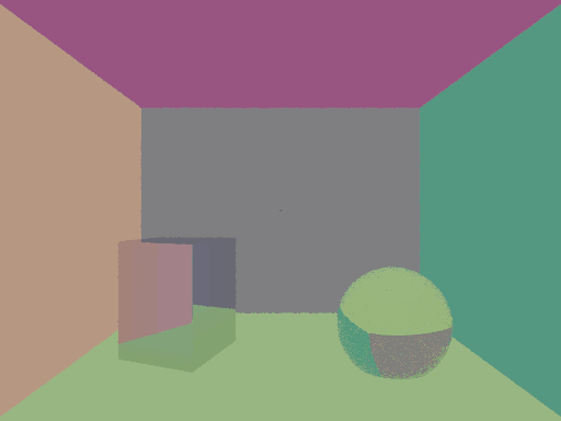
Now working on the ideal diffuse (Lambertian) BRDF, it is interesting to notice that I had to write a ton of new functions.
Along with a variety of random sampling utilities, which make use of the C++ <random> header, I also had to write a householder reflection function.
If you don't know, the householder reflection matrix F for a vector x satisfies F * x = length(x) * e1 where e1 is the first standard basis of the space.
Why do I need such a function?
Well, when a ray strikes a surface, suppose we want to uniformly sample the ball in the 3d space orthogonal to the surface normal.
What is this subspace?
If we have an orthonormal set of basis vectors, with one such vector being the surface normal, then we can instantly transform the standard unit ball to one in a space orthogonal to the surface normal.
This is why we need a householder reflection matrix: it gives us the orthonormal bases that we want.
Now let us delve into 4D Lambertian materials.
First off, it is very important to understand the 3D Lambertian BRDF. I spent some time reading the following two articles: (Ocean Optics), (Lambertian BRDF derivation). What I learnt is that in the BRDF, we divide by π (and not 2π as I would have expected) in order to ensure that we have no energy loss when albedo is 1. The BRDF is simply constructed in order to ensure that. But more importantly than that, I think I gained a better understanding of why the cosine sampling method works for 3D.
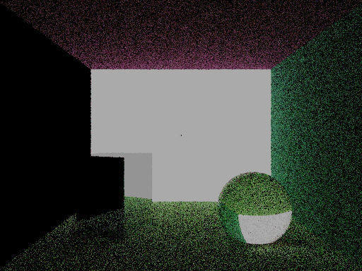
Because of this, I am able to simply use the equivalent of disk sampling for the 4D case. I made the back facing wall a light source and all of the walls Lambertian, and rendered to get this image:
--- Day 17 ---
Aug 01 2025Okay, so let's talk about what sort of image I produced yesterday. As expected, with 5 samples, we have a lot of noise, especially since our search space is huge too. Additionally, there is a single black pixel in the center of the light source on the back facing wall. But... more than that there seems to be a jarring problem.
The entirety of the left wall is not illuminated at all.
Luckily, I am pretty sure I know why this is the case; it's because of numerical stability with the householder reflection matrix.
It is important to note that this effect is only hapenning on the wall with a normal pointing in the standard i direction (the direction of e1).
In this case, we end up dividing by a very small, maybe zero quantity.
To avoid this, I have to change the way I calculate the Householder reflection.
To ensure numerical stability, the ideal method is that if we are too close to +e1, then we instead use -e1 and negate the resulting matrix.
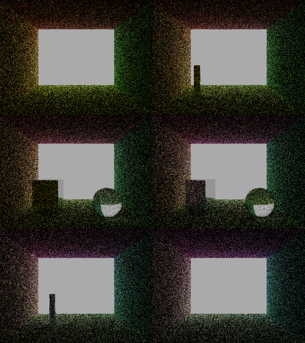
Now, the noise should be significantly reduced when many more samples are taken. I will begin work on the microfacet model for glossy models. I spent a lot of time researching the microfacet models. Here are some of the sources that I used to do the research.
Now we know that the mircofacet model consists of various terms. We can express it as the sum of a diffuse term and a specular term (consisting of a Fresnel reflection component, a distribution function, and a shadowing function / geometry term).
So how will we adopt this to 4D? Well, one thing is that I am interested in glossy and reflective materials, so I would like to get rid of the diffuse term to get closer to a metalic gloss. The second thing is that the Fresnel reflection term is something that (for metals) is based on the properties (colour) of the metal and always takes a value between 0 and 1. The distribution term is something very vital, which we can use the GGX distribution for. Finally, there is the last aspect of how to represent the shadowing term. Traditionally, in 3D this is represented by a term that considers how close to grazing the light is, and then reduces the BRDF output if we are close to grazing.
Okay, so now that we have an idea of the 3D way of things working, I will explain what we can and cannot reaonsably do in 4D.
Firstly, the specular term in the 3D microfacet model is divided by 4 * dot(N, L) * dot(N, V).
It is not immediately clear to me how to determine an equivalent expression for 4D.
There are definitely some 4D integrals involed and to be honest, I don't understand the derivation of the 3D microfacet model BRDF to derive one for 4D.
Thus, I am forced to make certain further simplifications to make this easier.
As with the implementation of the Lambertian BRDF, I will rely entirely on sampling.
This is to avoid the calculation of the BRDF so we can easily ensure that there isn't an addition of energy into the scene.
To this end, I implement the sampling of a mircofacet normal m according to the GGX distribution around the surface normal n.
We keep resample according to a probability given by the geometric term of the generated microfacet normal.
The probability that we resample is given by the formula for the Geometry term (using the Schlick-GGX approximation) given in the video.
Then, reflection is conducted with colour transmitted according to the coefficient given by the Fresnel term.
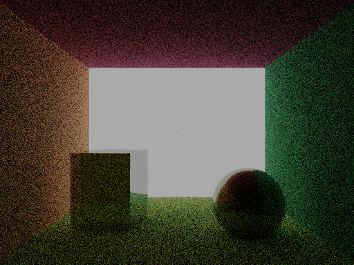
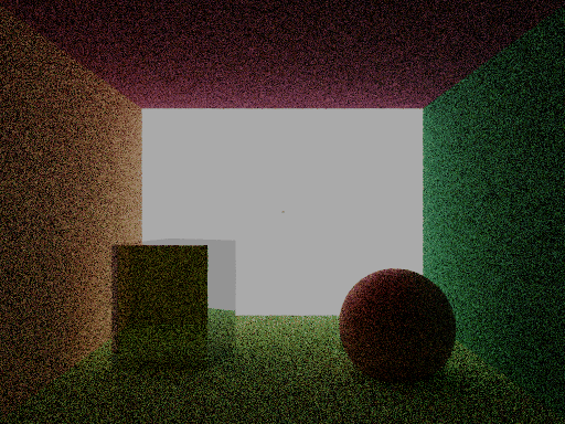
I was originally intending to use the Beckmann distribution for sampling, but even though the distribution might be harder for GGX, the geometry term is easier written. Here are some results of the microfacet model where the sphere on the right is shiny (shaded with the microfacet model).
--- Day 18 ---
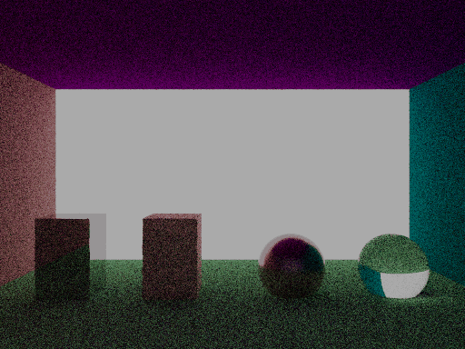
Aug 02 2025The way I implemented microfacet lighting models is equivalent to the typical way in 3D from what I understand, but it has the downside of being problematic when the roughness is close to 0. This is because with low roughness, we may have to often resample and this is problematic in edge cases when we have incoming rays which are grazing. Here is a render involving a wider scene with more objects of different materials, and the walls are Lambertian diffuse as always.
Volumetric Fog
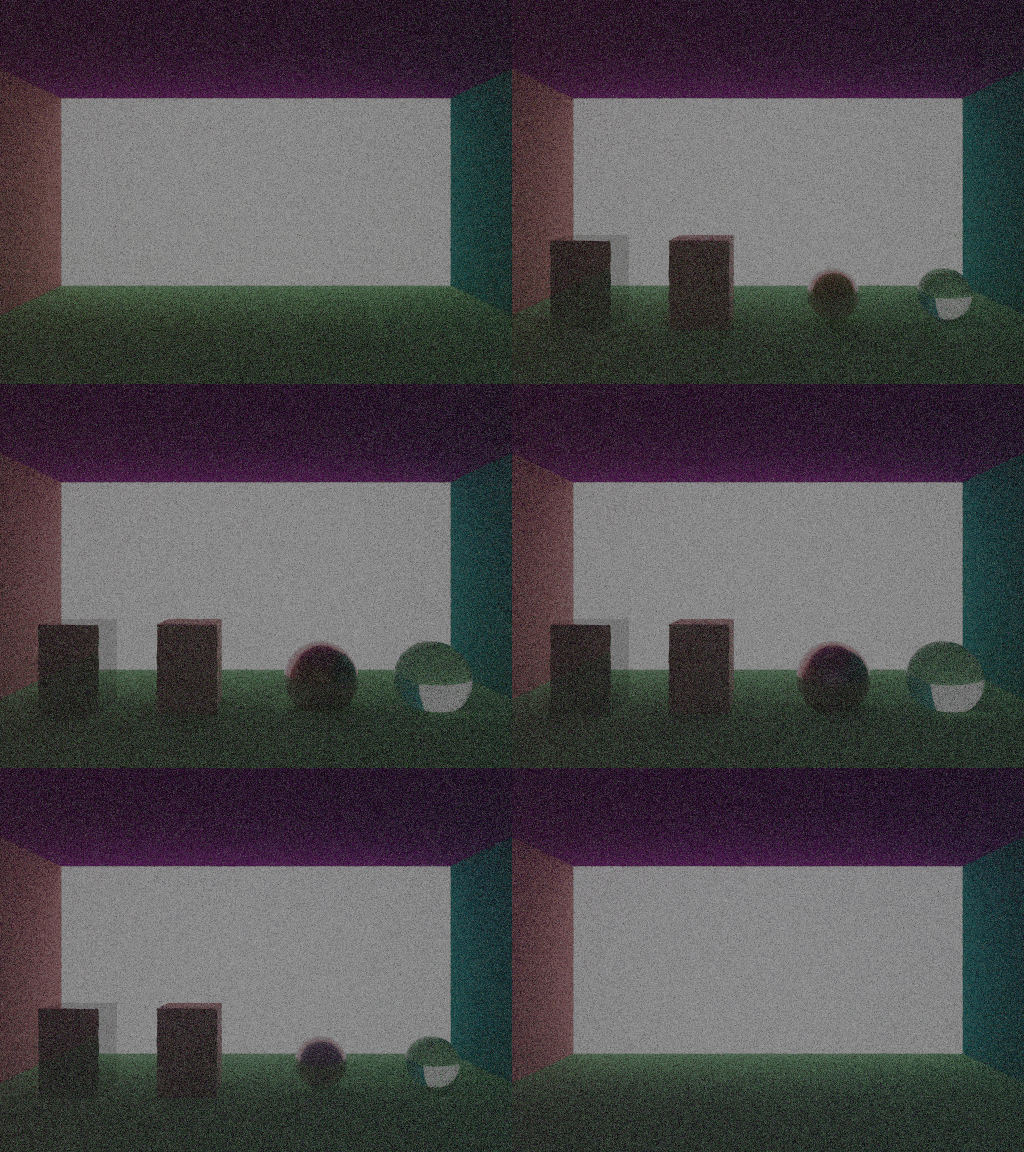
Volumetric fog consists of two components: extinction (via scattering and absorption) and scattering in. The laws for volumetric fog are much easier to work with given homogenous mediums, so I assume that all glass and air mediums are homogenous and defined via medium map in a way that is not based on normals.
Typically, we sample a distance from an exponential distribution, and we check if the sampled distance is more or less than the distance to the next hit.
If it is more, then we hit as normal, and if it is less, then we scatter the light and multiply by the extinction coefficient given by exp(-σ_t * t) where σ_t is the extinction coefficient of the homogenour material we are in, and t is the distance we just sampled (and travelled).
To implement this in raymarching, we have to keep track of two quantities as we step: the distance allocated for us to travel in the current direction (generated according to random exponential distribution based on the current medium), and the distance we have already stepped in the given direction. Additionally, there is the question of how to scatter when we hit a particle. The simplest answer, and the one I chose to implement is to simply choose a new direction at random.
One problem I seem to have is that too many of my rays die too early without reaching a light source. This is because with a set number of permitted steps, the amount of computation for a simple path is greatly increased. This makes the renders dark, like we might have already seen. When the extinction is high, the likelyhood that particles make it to a light source at all is very very negligible. And since I don't have NEE (due to not having information about where light sources are...) volumetric fog will cause darkness.
Denoising
I have looked at two denoising algorithms, and believe that for my purpose, the ideal method would be using the median filter. In order to implement a median filter, there has to be knowledge of the the final render already. To this end, I am required to store all of the rendered frame information before actually displaying it.
I have thus refactored the camera code to become more readable and controllable via just the elements of the Camera struct. Towards this, the camera consists of a start position, end position, current frame number, and final frame number. With this information, it is possible to get the information about what to render onto what frame.
So, I have implemented the median filter algorithm, which requires a step after completely rendering everything to recalculate all of the pixel values. Here are the two previous scenes but with the median filtering.
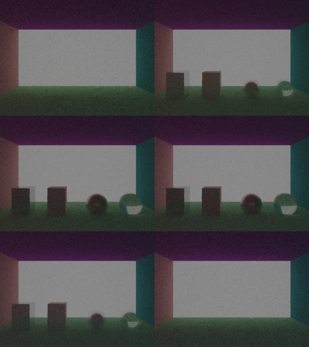
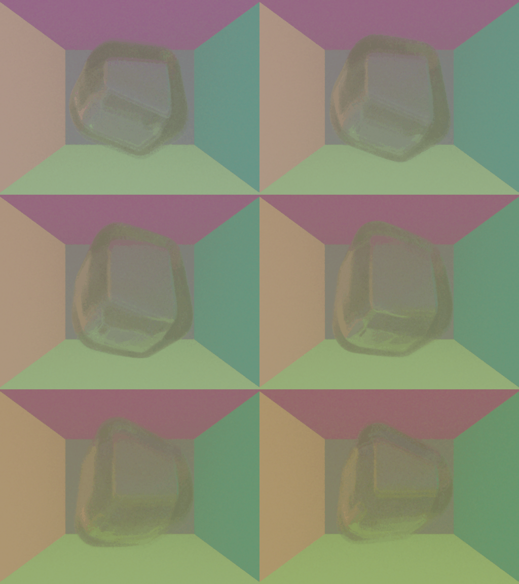
As you can see, there is definitely a difference that is observable. But the result of the algorithm isn't exactly what we wanted. While the algorithm seems to be effective in obtaining a clearer, less visually jarring image, we seem to be getting blurr, which is somewhat expectable. The difference between figure 27 and 29 seems to show this. We see that the glass hyperbox is blurry in figure 29.
Preparing for Final Project Submission
--- Day 19 ---
Aug 03 2025For the final project submission, I choose to submit 3 scenes, namely the scenes depicted in figures 26, 27, and 30.
